In this work we analyze the effect of IR. Dynamic Power Drop Dynamic IR dropir drop is calculated with the help of the switching of the cells.

Team Vlsi Decap Cells In Physical Design Use Of Decap Cells In Pd
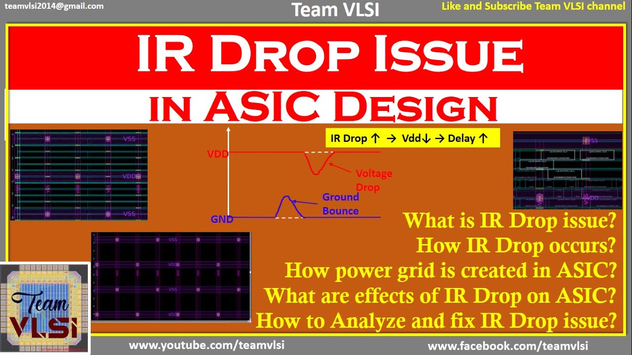
This resistance consumes power causing voltage drop ieIR drop.
. Static or Dynamic IR Drop is proportional to the current flowing through the power grid. So dynamic IR drop will be addressed. IR drop determines the level of voltage at the pins of standard cells.
Provide more number of wire 2. IR Drop is Signal IntegritySI effect caused by wire metal resistance and current drawn off from Power Vdd and Ground Vss grids. Email ThisBlogThisShare to TwitterShare to FacebookShare to Pinterest.
We cant have functional failure in our design. Load splitting can reduce the peak current demand from the power grid. Lecture 6 2 RAS Lecture 6 3 Clocked D Flip.
Floorplanning is the first stage in physical design. Increases skew Use different power grid tap points for clock buffers but it makes routing more complicated for automated tools Use smaller buffers but it degrades edge ratesincreases delay Rearrange blocks More VDD pins Connect bottom. Amount of current drawn from the power grid is directly proportional to the output capacitance thats being driven.
There are two types of IR drops. We can improve dynamic IR drop by below methods. The delay changes and the reduced supply voltage of the cells in turn affect power consumption in the design.
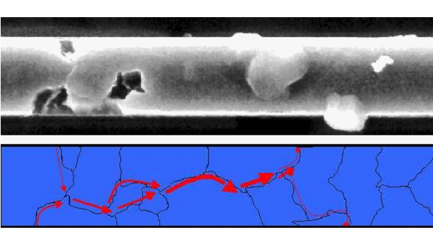
What are the different types of delay models. Similarly in dynamic analysis high transientswitching current can lead to high Dynamic. The purple waveform represents the voltage waveform after decoupling capacitor insertion.
IR drop while causing an increase in delay for a digital transistor can have an even bigger impact on analog circuitry. Remedies Stagger the firing of buffers bad idea. In the previous article we have discussed the physical design flow and sanity checks before the floorplan.
So to avoid any kind of functional failure due to Dynamic IR we use Decap cells in our design. Vlsi pnr cts physicaldesign mtech cadence synopsys mentor placement floorplan routing signoff asic lec timing primetime ir electromigratio. What Is The Importance Of Ir Drop Analysis.
B Allowable IR drop. Posted by Unknown at 1143. Value of acceptable IR drop will be decided at the start of the project and it is one of the factors used to determine the derate value.
Calculates the average voltage drop of entire design assuming current drawn across is constant. However decaps are leaky and it will add to the leakage power in the design Splitting output capacitance. Not only can timing change but it can directly cause functional failures.
IR Drop is Signal IntegritySI effect caused by wire metal resistance and current drawn off from Power Vdd and Ground Vss grids. Placing dcap cells in between them 2. C Global route congestion.
IR Drop Analysis in Physical Design IR Analysis in VLSI. Caused by cell currents. Typically power consumption is lower when IR-drop effects are considered.
In this article we will discuss what are the inputs required to begin the physical design. Static IR drop analysis. Value of acceptable IR drop will be decided at the start of the project and it is one of the factors used to determine the derate value.
IR-drop power and signal reliability have become as important or more important as chip area which was a prime concern for previous technologies. The ideal supply voltage is set to 12V. Inputs required for physical design can be categories broadly into two types.
D Physical information of the design. Increase the width of wire 2. IR core 775 mV IR package IR pads 5 To determine values for IRpackage and IRpads consider that IRpackage consists of two components.
Without this change timing calculation. There is a resistance associated with each metal layer. Given that the current draw of a wire is influenced by activity in other areas of the chip it is often seen as a source of noise for the analog circuitry and this has to be taken into account.
This is shown in the blue waveform. If IR drop is moredelay increases. Flip-flop setup and hold times clock power clock latency skew jitter impact of IR drop on clock clock layout and routing clock synchronization.
High average current can cause for high Static IR Drop. If the value of IR drop is more than the acceptable value it calls to change the derate value. An IR drop on the power and ground rails affects cell delaysthe higher the IR drop the slower signal changes propagate through cells.
If the value of IR drop is more than the acceptable value it calls to change the derate value. Methods to Improve static IR drop 1. IR Drop analysis Static and Dynamic.
What Is The Importance Of Ir Drop Analysis. There are two types of IR drop analysis namely. Current I Increases near inductor so L dIdt increases due to which Voltage drop across Inductor increases hence less voltage at the partition or logic group or registers is seen in the design.
And the areas and relative positions of blocks are determined and various. In this paper we address IR-drop problem in floorplanning stage. A WLM wire load model b NLDM non linear delay.
The peak voltage drop is now reduced and well within the tolerance level. The peak drop in the voltage waveform before decoupling capacitor insertion exceeds the tolerance voltage level. Package cross-section showing IR drop components Combining 3 4 and the value for IR chip found in 2 provides a formula for determining an actionable IR drop target for the physical design process.
IR drop causes voltage drop which in-turn causes the delaying of the cells causing setup and hold violations. Design of the clock and the flops are related to each other so they should be studied together Design Issues. What is IR drop.
Increase the no of straps. IR-drop has become a major source of delay defects in deep sub-micron VLSI designs. How it affects timing.
Hold violations cannot be fixed once the chip is fabricated. Calculation related to IR drop 1. IR drop determines the level of voltage at the pins of standard cells.

Power Planning Vlsi Physical Design For Freshers
Understanding Electromigration And Ir Drop In Semiconductor Chip Design Challenges And Techniques Ele Times

Vlsi Basics Electromigration Ir Drop
Ir Drop Issue In Vlsi What Is Ir Drop In Asic Why Ir Drop Effects Of Ir Drop Youtube

Team Vlsi Ir Drop Analysis In Physical Design Ir Analysis In Vlsi

Team Vlsi Ir Drop Analysis In Physical Design Ir Analysis In Vlsi

Team Vlsi Ir Drop Analysis In Physical Design Ir Analysis In Vlsi

Power Planning Vlsi Physical Design For Freshers
0 comments
Post a Comment